As noted in our post Finally Back, we downsized and moved this past January. At that time, the development we moved into consisted of the shaded area in the diagram below, but the development was only 1/3 complete. Much of our entertainment since the coronavirus restricted our outside activities has been watching the construction of new streets and new houses in our development. For example, Street E had been finished except for final paving and there have been four houses built there, and we’ve watched them add utilities, curbs, gutters, and sidewalks to Street F which has had the first paving.
The development plan shows a another street, Street G, which will become another entrance to the development at one end and wrap around to Street D. Also, Street B, the cross street, will be extended past Streets E & F to access Street G and then three more streets ending in culs-de-sac.
A month ago we saw a large drill (later two drills) working in the north end of the field beyond the Street E. Since then, I’ve talked to several of the drilling and blasting team members a number of times and learned that there is a ridge of rock that runs parallel to the main road which runs past the development. They were drilling to blast trenches for utilities (water and sewer) and to remove a high area for Street G, working from the north and around to Street D.
In this area, the rock is only about one foot beneath the surface of the field and they were drilling 3-1/2″ diameter holes about 9′ to 10′ deep. The main rock ridge is primarily hard bluestone, which is a blue tinted limestone. The ridge transitions to a softer layered bluestone composition away from the main ridge. Farther away from the primary ridge, they were only drilling the utility trenches with some crossovers to allow the pipes to cross under the road.
I had never used my camera for video prior to the video I took of the first blast – the camera was handheld, there was more camera movement than I expected, and I wasn’t aware of all of the optional camera settings. There is a link to this video in the Additional Information section below. I missed taking a video of the second blast but got still photographs afterward.
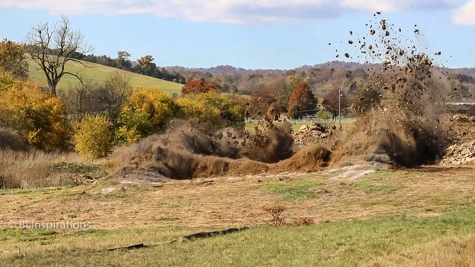
For the third, fourth, and fifth blasts, I used a tripod from good viewpoints and got very good results. These videos are HD video, which has better resolution and shows more detail. The featured image (above) is a single frame of the fifth blast video.
Update 11/4/20
Today there was another blast (Blast 8) that I was able to capture on video. That video has been added below, after the fifth blast video.
Drilling Machines
The drilling machines are made by John Henry and have a 20′ hydraulic hammer drill boom mounted on a Caterpillar excavator platform. The drill includes an air compressor for flushing rock chips from the hole with water added to suppress dust. The operator can adjust the tilt angle of the boom and internal readouts indicate the depth of the drilled hole. On this project, each drill can complete about 100 – 3-1/2″ diameter holes per day. These are photos of the drills.


Blast Area and Explosives Set-up
For this project, the drilled holes are 6′ apart in rows, with the rows 6′ apart. In the areas where they have been blasting both trenches for utilities and the roadway, there are 13 drilled holes in each row, including two holes for each utility trench. After they drill an area, they insert small cones in each hole to keep the hole dry. In each cone there is a slip of paper indicating the depth of the hole and the depth of the rock beneath the surface. The blasting engineer uses this information to determine how much explosive material to add to the hole. (Please see the first three photos in the gallery below.)
The blasting technology in this project uses non-electric shock tubes (which are are used to send a detonation signal to a detonator) instead of wire and electric detonators which are sensitive to stray electrical current caused by static electricity or radio frequency energy, so they are safer to use. Shock Tubes are small-diameter hollow plastic tubing with a coating of explosive material on the inner surface used to transport an initiating signal to an explosive by means of an explosive shock wave which travels the length of the tube at about 6500 feet/second without bursting the tube. The shock signal can be transferred to other shock tubes via a clip with an integral delay detonator to excite the next shock tube. (The seventh photo in the gallery below shows two shock cords connected with a clip and the eighth photo shows a shock tube and its clip after the detonation.)
Each drilled hole receives a small high-explosive “booster” which provides the energy to initiate the primary explosive. A non-electric delay detonator with a length of shock tube attached is inserted into the booster. This shock tube is terminated at the other end with a delay connector which, in turn, is connected to another shock tube. A typical delay for the detonator at the booster is 350 ms while the connector delay is 25 ms.
These delays allow the blasting engineer to control the explosion’s pattern by controlling the timing of the individual explosions using the interconnection of various shock tubes and detonators. (The fourth photo in the gallery below shows a booster charge with its shock tube and detonator installed.)
The primary explosive material is an ammonium nitrate based liquid emulsion that looks like thin strawberry yogurt. It is mixed from non-explosive ingredients on site and delivered to the drilled hole via a hose from a pump on the mixing truck. The blasting engineer controls the amount delivered to each hole. After the measured amount of liquid is delivered to the holes, each hole is filled with crushed stone. (These are shown in the fifth, sixth, and seventh photos in the gallery below.)
When the blast area is near existing structures (about 100 yards) the blasting engineer positions a portable seismometer near the structure to confirm that the blast vibrations were safe for the structure. (The ninth photo in the gallery below shows the seismometer.) In addition, blasting mats are used in these instances to minimize flying debris near existing structures.
After the holes have been drilled, it takes a half dozen personnel about five hours to load the holes with explosives and make all of the shock tube connections.
When blasting mats are used, they are laid over the prepared blast site after the explosives are in place and the shock tubes have been connected. The blasting mats used on this project are about 10′ by 12′ and are made from used automotive tires laced together with steel cables. A closeup of a blasting mat is the 10th photo in the gallery below, photo 11 is a blasting mat being loaded onto a truck for the 10th blast, while photos 12 and 13 show the blasting mats after the 10th blast.


Blasting Videos and Photos
In these videos you can hear the individual detonations as the blast progresses. Also, there are links to the first and third blast videos at YouTube (which are not shown here) in the Additional Information section below.
To view any of these videos in slow motion, adjust the Playback speed in the YouTube video’s Settings (the gear icon) and select HD in Quality if it’s not automatically set. Suggestion: advance the cursor to just before the explosion before you view it in slow motion.
Fourth Blast Video
The fourth blast was the largest to date: 418 holes or an area about 78′ deep by 192′ wide. This blast started at the right-rear corner and progressed to both the front and the left. (Watch a larger version of this video at YouTube: https://youtu.be/sxtY9VOyQuU.)
Fifth Blast Video
The fifth blast was for utility trenches on both sides of the road with some crossovers so the blast pattern looked like a ladder. For this video we were on a rise looking toward the end of the blast, which started on the other side of the previous rise. (Watch a larger version of this video at YouTube: https://youtu.be/i9yTxovKFTg.)
Eighth Blast Video
The eighth blast was for the entire roadway at the beginning and then for utility trenches closer to the camera. For this blast the camera was on a rise about 75 yards from the end of the blast and I was under one of the drilling machines. (Watch a larger version of this video at YouTube: https://youtu.be/fY_xCRJuOTo).
Blast images
These are images and frame captures from the blasts I photographed.


Additional Information
Bluestone – Wikipedia – please see the last paragraph about bluestone in the Shenandoah Valley.