Background
In December 2023 I noticed a headline about pinhole photography in one of the many photography emails I receive or in one of the articles Google offers me on my phone. I have been aware of pinhole photography for a long time but never pursued it, preferring traditional photography. The headline may have mentioned making a pinhole camera from a removable lens DSLR, which triggered my interest, so I started thinking about that as a possible project. I also thought it might make a nice presentation for the camera club I am a member of.
I quickly discovered that there are many suggested ways to make a pinhole camera from a DSLR; some articles suggested modifying an old camera body, others didn’t take care to prevent damage to a good camera body. Several of them suggested using a camera body cap to mount the pinhole rather than doing something directly to the camera body itself, and that is the direction I choose.
History
A camera obscura (from Latin camera obscūra ‘dark chamber’) is a darkened room (or tent) with a small hole at one side through which outside scenery is projected onto a wall opposite the hole. The projected image is also referred to as a “pinhole image.”
One of the earliest known written records of a pinhole image is found in a Chinese text dated to the 5th Century BC, traditionally ascribed to Mozi, a Chinese philosopher. Another early account is provided by Aristotle, who is also thought to have used camera obscura for observing solar eclipses.
In 17th-century Naples, Della Porta spent most of his life dedicated to scientific endeavors. He was the first to experiment with manipulating the camera obscura’s projected images with the use of lenses. He invited others in Naples to witness his invention, but instead of marveling at his work, he was charged by the church with sorcery and his books were banned.
The first known description of pinhole photography is found in the 1856 book The Stereoscope by Scottish inventor David Brewster, which includes the description of the idea as “a camera without lenses, and with only a pin-hole”.
Pinhole Camera Basics
A pinhole camera is a minimalist form of photography, as there is no physical lens or focusing, just the image sensor (light sensitive paper, film or digital sensor) and the pinhole. This form of photography runs counter to everything used to take quality images with modern equipment; it is the photographic equivalent of impressionism.
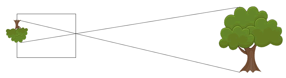
The simplest pinhole camera consists of a light-proof box with a small hole in one side. Light from the subject passes through the pinhole and projects an inverted image on the opposite side of the box which can be captured by an image sensor there. The size of the image formed by a pinhole camera is determined by the ratio of the distance from the object to the pinhole to the distance from the pinhole to the sensor. This ratio is known as the “magnification factor,” so increasing the distance between the pinhole and the sensor increases the size of the image on the sensor, as does decreasing the distance between the object and the pinhole, just like a longer focal length lens increases the image size (or magnifies the subject).
Suggested Pinhole Designs
A number of the articles I read suggested taping a circle of aluminum foil or a piece of flattened beverage can with the pinhole to the outside of the camera body over the lens mounting flange. Others suggested taping a piece of aluminum foil, a piece of brass shim, or part of a flattened aluminum beverage can with the pinhole to the outside of a camera body cap with a clearance hole drilled in the center to pass the light without obstruction. Almost all of these articles suggested blackening the inside of the pinhole to minimize light reflection inside the camera. I also found that commercially produced (chemically etched or laser-drilled) pinholes are readily available to provide a ‘perfectly’ round and smooth pinhole.
Pinhole Technical Information
This information can be easily ignored but is included for those who wants to understand the details.
Sharpness
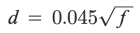
In 1857, Joseph Petzval calculated the optimum pinhole size as
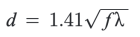
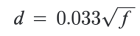
where d is the diameter of the pinhole, f is the focal length, and 𝛌 is the wavelength of light. For the middle of the visible spectrum, which is 550 nm or 0.00055 mm, this equation can be reduced to:
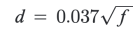
In 1891, Lord Rayleigh (incorrectly) calculated that based on the diffraction of light, the pinhole diameter for optimal resolution of subject at infinity for a perfectly round pinhole is:
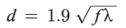
where d is the diameter of the pinhole, f is the focal length, and 𝛌 is the wavelength of light. For approximation, any subject distance over 10 focal lengths can be considered at infinity. For the middle of the visible spectrum, this equation can be reduced to:
The general form of Lord Rayleigh’s equation is:
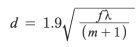
where d is the diameter of the pinhole, f is the focal length, λ is the wavelength of light, m is the magnification factor, calculated as m = f / D where D is the distance from the pinhole to the subject (all in mm).
In 2004, Kjell Carlsson (Professor Emeritus of Imaging Science and Photography at KTH Royal Institute of Technology, Stockholm) observed that perceived sharpness also depends on contrast and calculated the optimal pinhole diameter as:
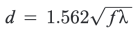
or
Many pinhole camera articles reference Lord Rayleigh’s equation without mentioning the others and my initial pinhole selections were based on that. Later in the project I made more pinholes in an attempt to see which was the sharpest.
Aperture size (f-number = N)
N = f / d
where f is the focal length and d is the diameter of the pinhole
Focal Length
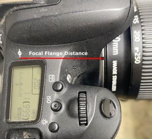
The focal length of a DSLR pinhole camera is essentially the Focal Flange Distance (FFD) of the camera, which is the distance between the lens mount and the image sensor plane. Most cameras have a symbol that indicates the location of the image sensor plane. For Canon cameras this distance is 44 mm. If I add my 68 mm macro extension tubes, the focal length becomes 112 mm.
Considering the various equations above, the range of the optimum pinhole diameter is 0.22 to 0.30 mm for the 44 mm focal length and 0.35 to 0.48 mm for the 112 mm focal length. The effective aperture of a 0.30 mm pinhole for the 44 mm focal length would be about f/180 and the effective aperture of a 0.48 mm pinhole for the 112 mm focal length would be about f/290. I have not tried to measure the aperture to confirm these values.
Optimum Pinhole Size and Location
Within limits, a small pinhole through a thin surface will result in a sharper image but a dimmer projected image. An extremely small hole, however, can produce significant diffraction effects and a less clear image due to the wave properties of light. The contrast of the image also affects apparent sharpness, so as noted in the Pinhole Technical Information section above, there are a number of published calculations for the optimum pinhole size based on the effective focal length (the distance between the pinhole and the sensor). Vignetting (darkening of the corners of an image) occurs as the thickness of the material in which it is made approaches the diameter of the pinhole, because the sides of the hole obstruct the light entering at anything other than 90 degrees.
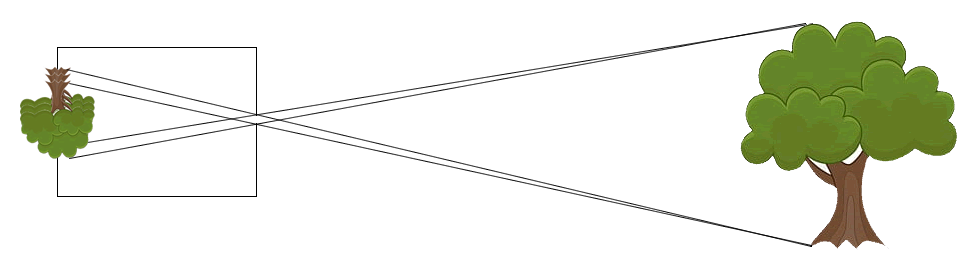
Large pinholes will result in blurred images because light from one point on the subject can reach more than one point on the sensor as shown in the second diagram.
The best pinhole is perfectly round (since irregularities cause higher-order diffraction effects which distort the image) and is created in an extremely thin piece of material. Industrially produced pinholes benefit from laser drilling, but a hobbyist can easily produce pinholes suitable for experimental or artistic photographic work.
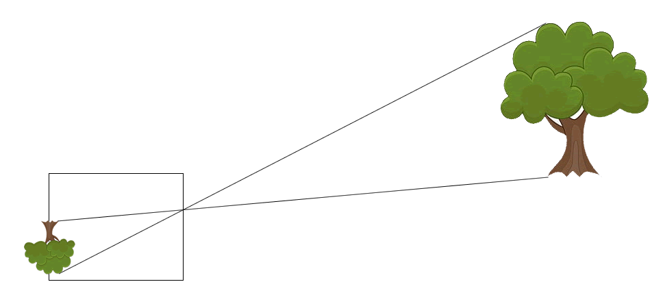
If the pinhole is not centered with respect to the sensor, the image will be offset as indicated in the diagram below. The variation in the location of the pinholes used to make the images in the Pinhole Images section below accounts for the slightly different fields of view of the resulting images.
My Requirements and Design Decisions
After reading a number of articles about making DSLR pinhole cameras, I formulated several requirements that my design must include:
- The pinhole mounting method must not damage the camera body or affect normal operation of the camera
- The pinhole must be easily replaced with an actual lens for comparisons
- Pinholes must be easily replaced to compare different pinhole sizes and configurations
Once I had identified these requirements, I made a number of decisions about the design, some of which became more obvious after I actually started work on making pinholes. These decisions included:
- I would not simply tape the pinhole to a body cap. Instead, the pinhole would be mounted on a substrate that fits snugly inside a body cap to make it easily replaceable, so I could compare different pinholes and to compare pinholes to lenses.
- Initially, I used aluminum foil as it is easier to make a small hole with a pin. Later, as I gained more experience, I made pinholes from pieces of aluminum beverage cans.
- I had read warnings not to use any adhesive materials which could outgas and affect the internal components of the camera (see Precautions below), so I would use epoxy cement and electrical tape for mounting the pinhole material to the substrate
- Once I created the substrates, I realized I would need a method to remove them from the body cap, so I added a piece of electrical tape to each substrate to form a pull tab to remove the substrate and pinhole from the body cap.
For my DSLR pinhole camera with the pinhole mounted on a substrate inside a body cap, the focal length includes the additional depth of the body cap less the thickness of the pinhole and substrate. This focal length is still about 44 mm and the focal length with the 68 mm extension tubes is 112 mm.
Construction Steps
These steps are described and illustrated with the images below:
- Create a substrate template to be used in the subsequent steps
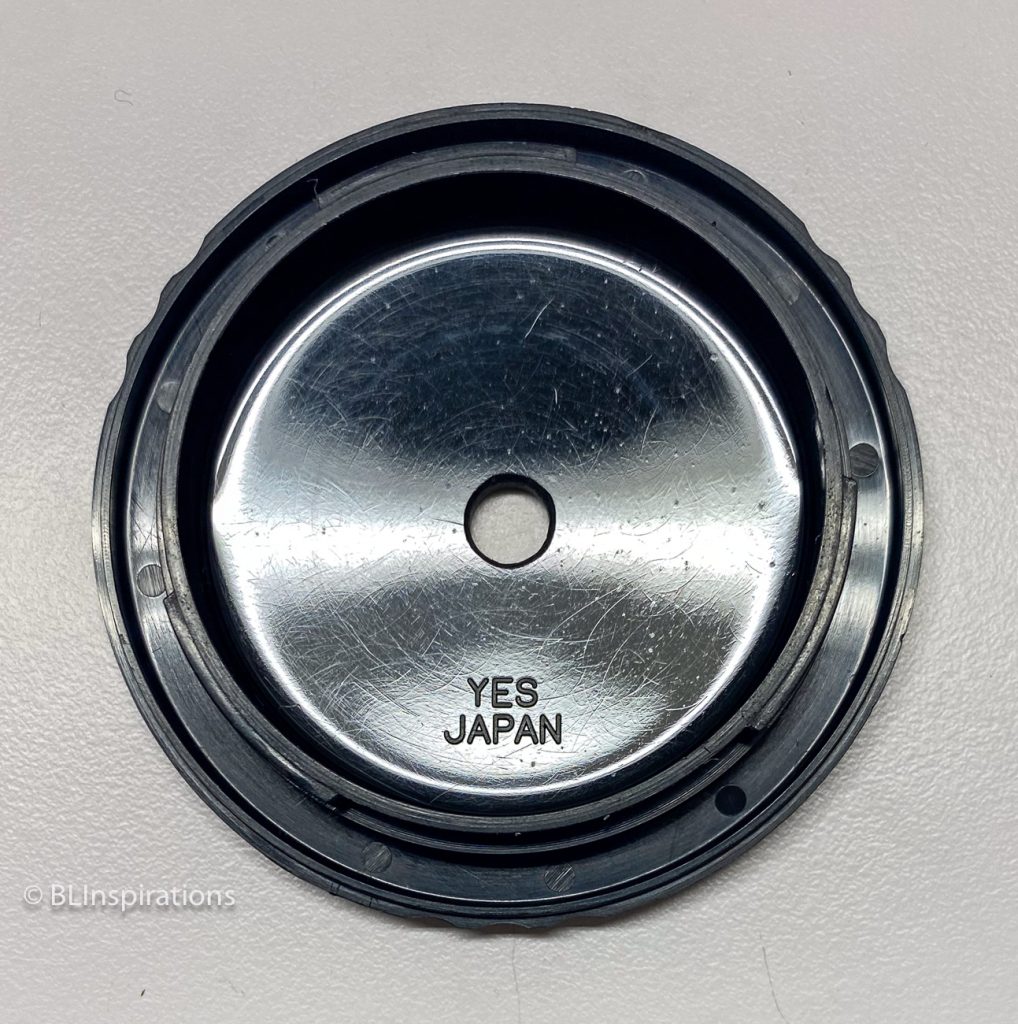
- Mark and drill a ¼” hole in the center of the body cap
- Mark and cut separate substrates for different pinholes
- Make a ¼” hole in the center of each substrate.
- Blacken the inside of the pinhole material to reduce reflections
- Adhere a pinhole to a substrate with epoxy or electrical tape
- Add a piece of electrical tape as a tab to remove the substrate and pinhole from the body cap
Precautions!
DO NOT USE cyanoacrylate-based adhesives (Krazy Glue, Super Glue, Permabond, etc.) on or anywhere near the camera! It outgasses for a long time after it sets and can leave a fine residue on the mirror, prism, lens, moving parts, and sensor. If you must use an adhesive, use a low-outgassing, fast curing epoxy, mix it well, and let it cure completely before getting it anywhere near the camera.
Create a Substrate Template
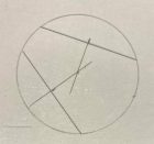
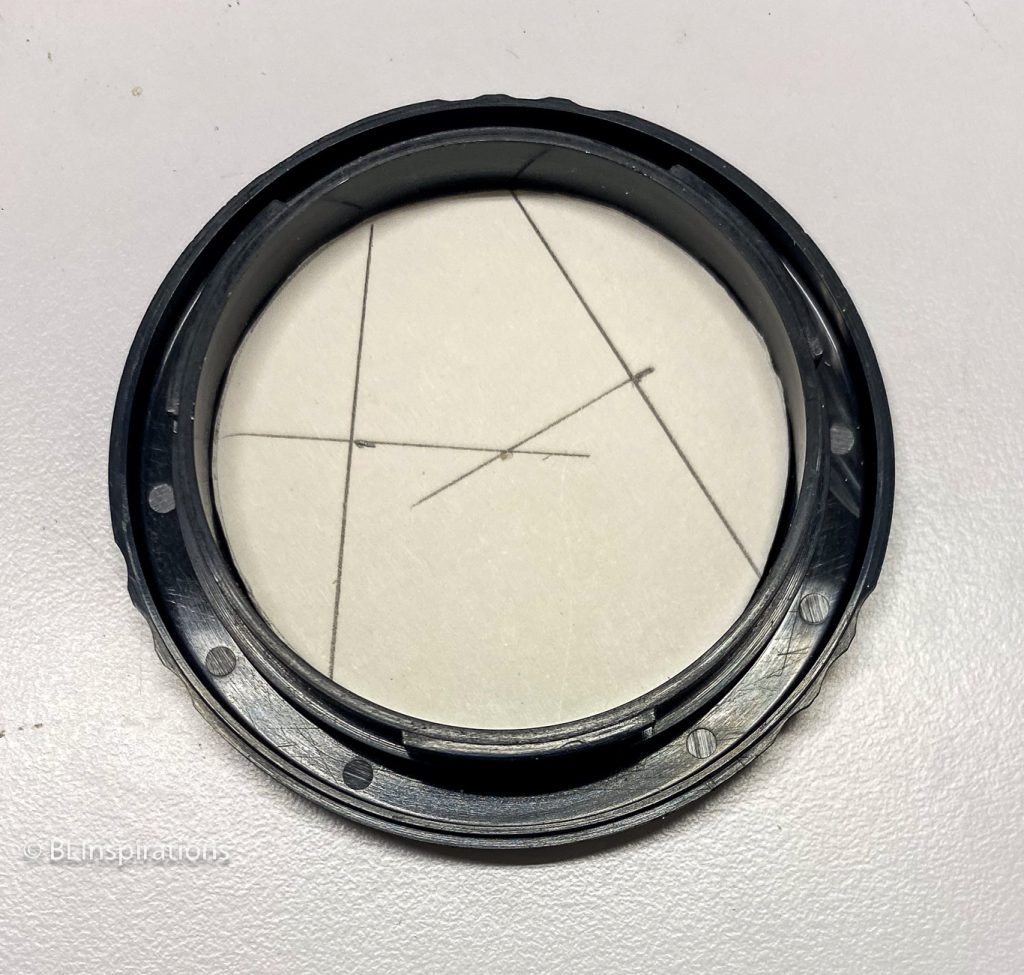
I used some scrap 1/16” mat board for the substrate template and the actual substrates. I measured the inside of a body cap and marked the template diameter with a drafting compass. I cut out the circle with scissors and trimmed uneven parts of the edge so it would just fit into the body cap. I then enlarged the compass point mark to mark the center of the inside of the body cap and the actual substrates. The pencil lines on the photo illustrate the alternate way to find the center of a traced circles using two chords.
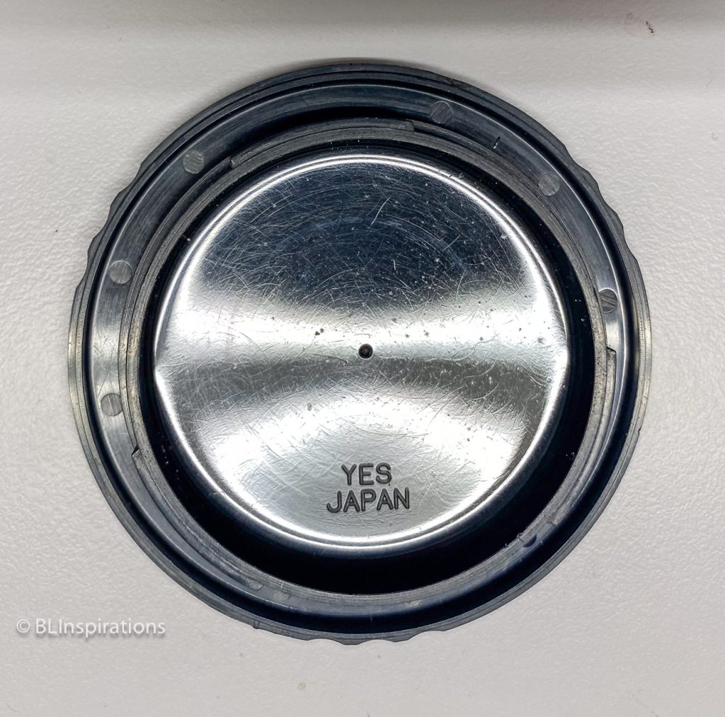
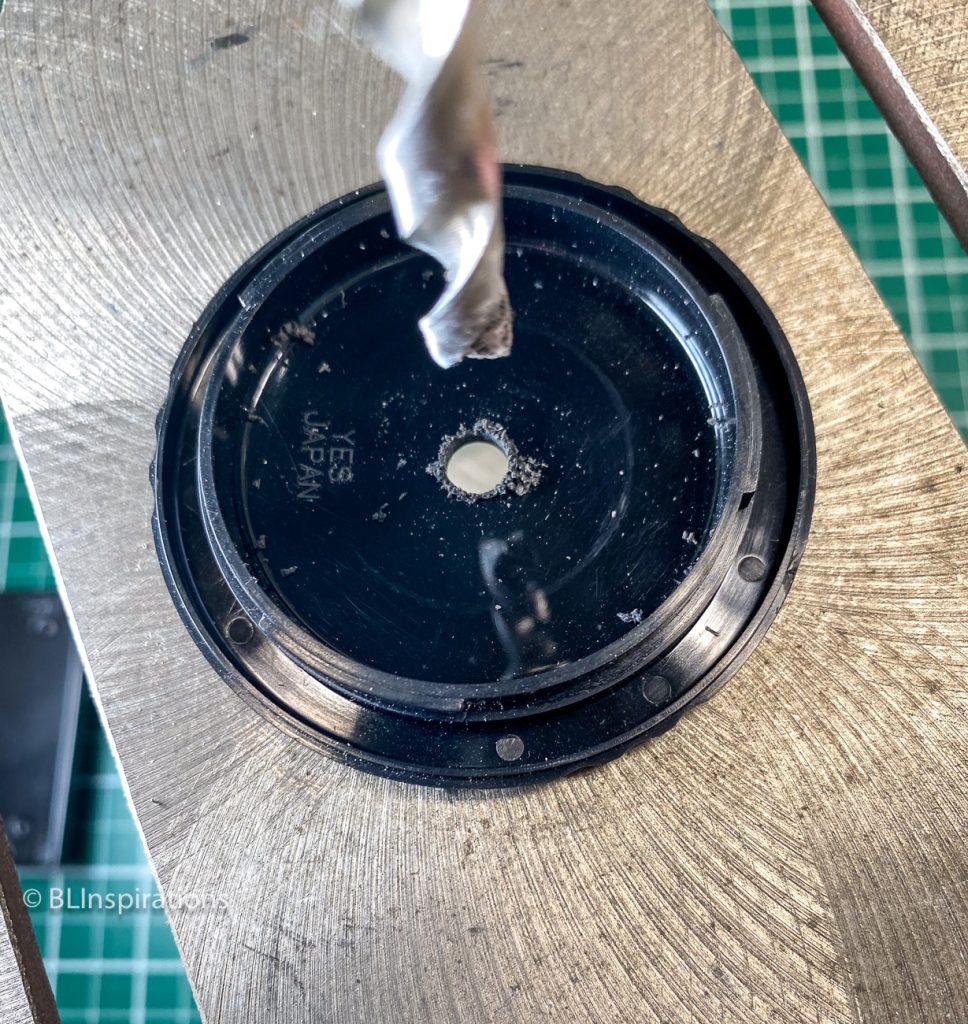
Mark and drill body cap
I inserted the template into a body cap and used a scribe to mark the center. I then used a drill press to drill a ¼” hole, deburred the hole, and washed the completed body cap.
Mark and cut substrates
I used the substrate template to draw the circles on mat board scraps and mark the center of each. I then cut the substrates with scissors, trying to stay just inside the pencil line. After cutting the circles I trimmed them as necessary to just fit within the body cap and then used a paper punch to make a clean ¼’ hole.
Measuring the Pinhole Diameter
To measure the pinhole diameters, I drew heavily on an excellent post I found at 35mmc.com: Making, Measuring and Testing the “Optimal” Pinhole: Pinhole Adventures Part 3 – by Sroyon. The procedure suggested there involved scribing two lines 5 mm apart on each side the pinhole and photographing them with a macro setup, then opening the photograph in Photoshop and using Photoshop’s guidelines to calculate the pinhole size. Instead of scribing lines, I used a 6” metric steel rule which allowed me to photograph a pinhole and the rule together which is a more accurate way to determine the 5 mm measurement, since I was unable to scribe straight lines and could not accurately determine where the 5 mm width should be measured. The pinhole diameter is calculated as the distance between the pinhole guidelines divided by the distance between the 5 mm steel rule guidelines x 5 mm.
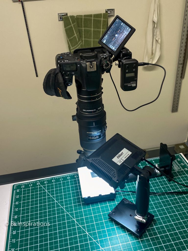
My macro setup has a focal length of 242 mm using a 105 mm macro lens with 68 mm extension tubes and a 1.4x teleconverter, with the subject at the closest focusing distance. This provides a magnification of nearly 2.8.
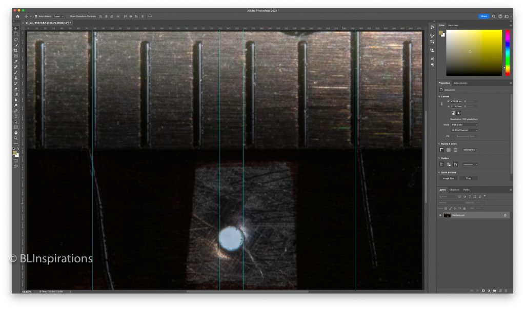
In the Photoshop screen capture above, the guidelines for the 5 mm measurement are at 395.4 and 78.6, the horizontal pinhole guidelines are at 260.5 and 231.5. The diameter of this pinhole is 0.46 mm, calculated as:
5 mm x (260.5 – 231.5) / (395.4 – 78.6)
Aluminum Foil Pinholes
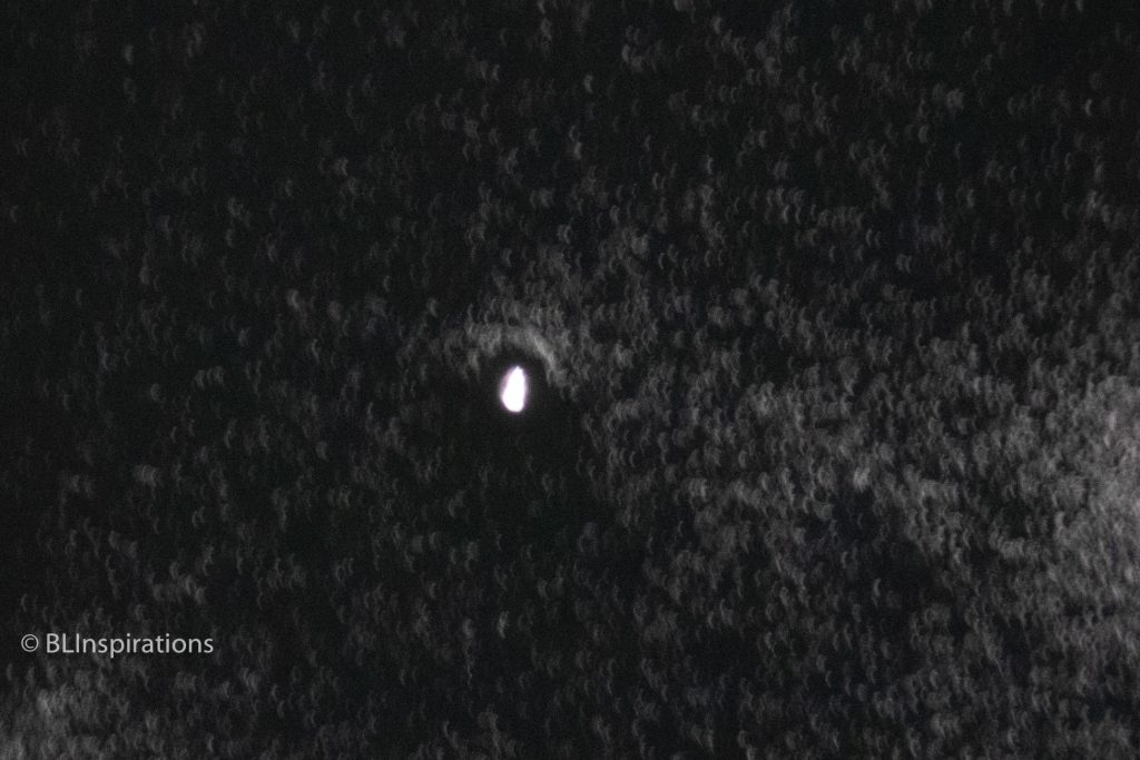
The thickness of regular aluminum foil 0.001” (0.025 mm) so it is easy to wrinkle and tear and must be handled carefully to not distort the pinhole. Also, since the pin is piercing the foil, it is easy to produce very irregular shaped holes instead of round pinholes, as shown in the photo below. Controlling the pin depth as described in the Aluminum beverage can pinholes section below produces more controllable pinhole sizes but can still result in irregular pinhole shapes.
To make aluminum foil pinholes, I sprayed the dull side of a piece of aluminum foil with matte black spray paint to blacken the sensor side of the pinhole. After the paint had dried, I used the template to draw the circles and mark the center points on the shiny side. After cutting out the foil circles, I used fast drying clear epoxy to mount one on each substrate. Once the foil was positioned, I smoothed it out as best as I could. Initially, after the epoxy had dried, I poked different holes in each of the foils from the shiny side with the tip of a fine pin. Many of these holes were irregular and the pinhole diameters were uncontrolled, so I later used thin pieces of cardboard to control the depth of the needle (and the diameter of the pinhole) as described in the Aluminum beverage can pinholes section below.
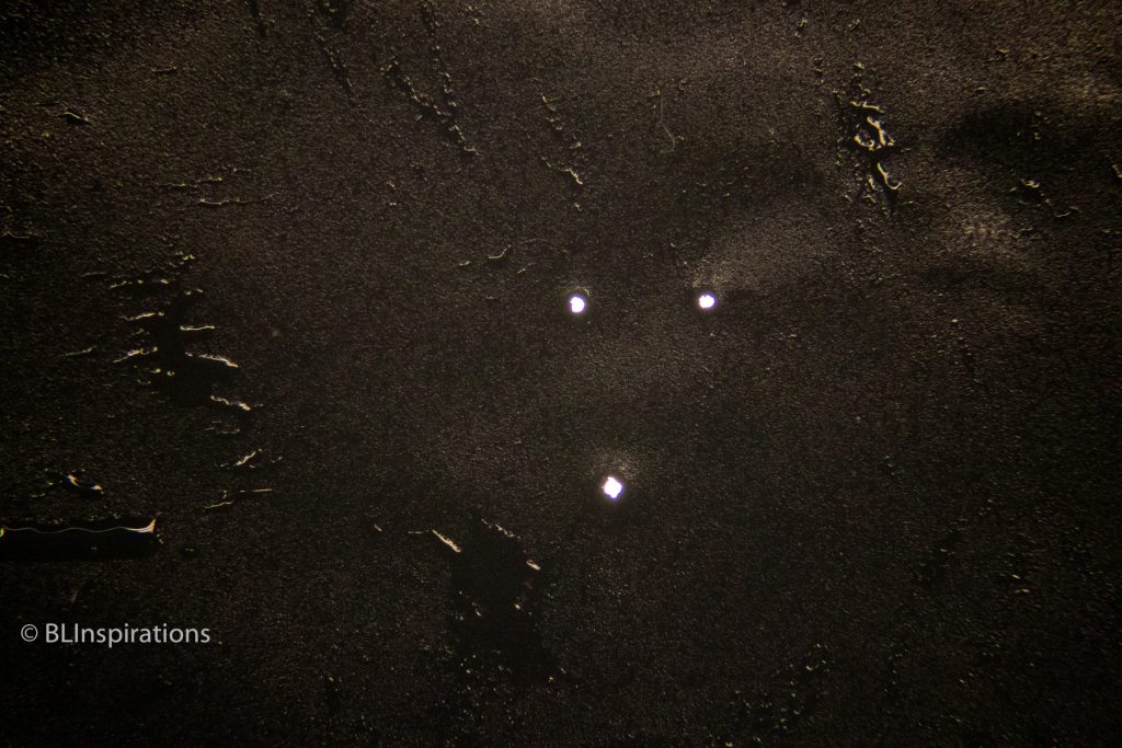
I had read that multiple pinholes would create unusual effects, so I put three pinholes in one foil substrate to compare with single pinhole photographs.
Aluminum beverage can pinholes
To make pinholes in aluminum beverage can material, I again drew heavily on the post at 35mmc.com – Making, Measuring and Testing the “Optimal” Pinhole: Pinhole Adventures Part 3 – by Sroyon. The metal thickness was 0.004” (0.10 mm) – still quite thin but not fragile like aluminum foil.
These are my steps for using pieces cut from a beverage can, using the requirements listed above:
- Cut pieces from an aluminum beverage can
- Make and smooth a pinhole
- Measure the pinhole to determine its diameter
- Mount the pinhole onto a substrate
I cut the top off a beverage can with a sharp utility knife and then used scissors to cut the can lengthwise and remove the bottom. I then flattened the remaining side of the can and cut it into approximately 1” strips. Finally, I cut the strips into approximately 1” square pieces and numbered them to track the pinhole measurements and results.
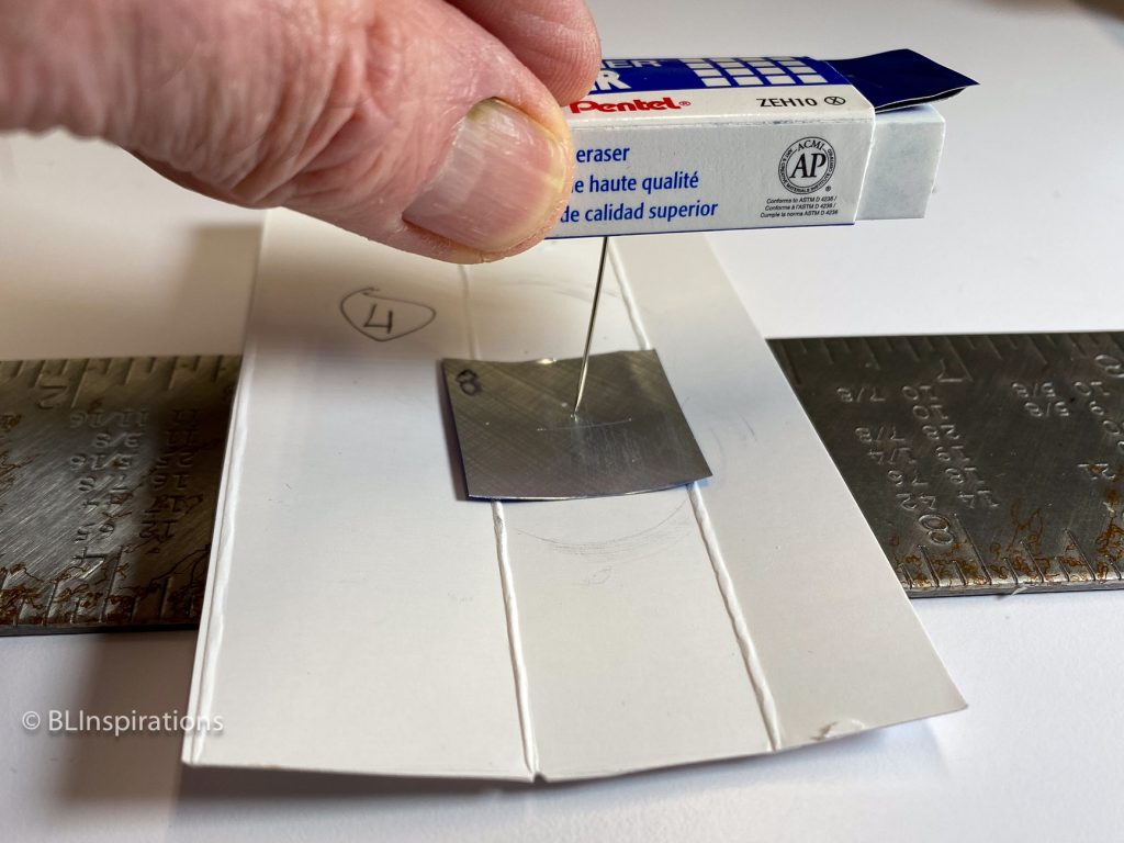
To make a pinhole, I embedded a needle in a rubber eraser and backed it with several scrap pieces of the aluminum beverage can. I then used various pieces of thin cardboard over a hard surface to control the depth of penetration of the point of the needle. The pinhole was made by pressing the needle into the aluminum square and then rotating the aluminum square to work the needle point through the metal.
Once the initial pinhole was made, both sides were sanded to remove the surface burrs, sanding the underside first. When I examined the resulting pinhole there were still burrs within the pinhole, so I lightly inserted and rotated the needle in the underside of the pinhole and then repeated for the top side. Initially, many of my pinholes were larger than I expected – I think I was pushing too hard when I reinserted the needle. I was more careful when finishing later pinholes, but I was still not able to predict the final diameter of the pinholes. I also made one very large pinhole with a diameter of 1.62 mm to illustrate the effect of a large pinhole on a photograph.

Once I had made a number of pinholes, I tried to mount them on substrates using fast drying clear epoxy as I did for the foil circles. Because the aluminum squares were not perfectly flat, I clamped several of them together to flatten them, but this introduced a problem, as several of the aluminum squares slid during the clamping process so that the pinhole was not within the clearance hole of its substrate. I tried to make more pinholes by taping the aluminum square to the substrate with electrical tape instead of using epoxy but keeping the pinhole centered in the clearance hole was still a problem.
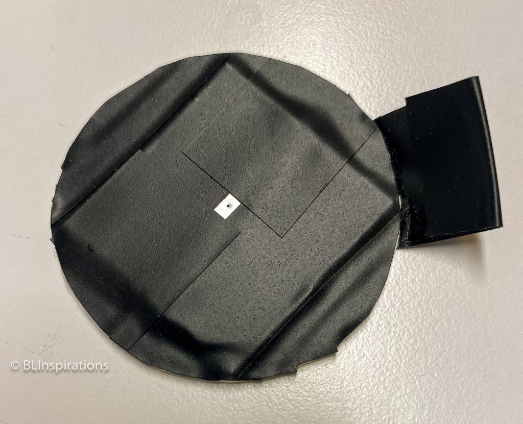
My final procedure was to put a small amount of epoxy around the edges of the aluminum square but away from the pinhole. I then placed the square epoxy side up on an LED light panel protected with wax paper, and then placed the substrate over the square using the light through the pinhole to center the pinhole with the substrate clearance hole. Finally, I taped the aluminum square to the substrate to hold it in place and to blacken the sensor side of the pinhole.
Commercial Pinholes
When I first looked into commercially produced pinholes, the cost was about $40 to $65, which is probably prohibitive for most amateur photographers just experimenting with pinhole photography. Later, I found some on eBay for $8 to $10, so I purchased 0.30 mm and 0.50 mm pinholes to compare with my others.
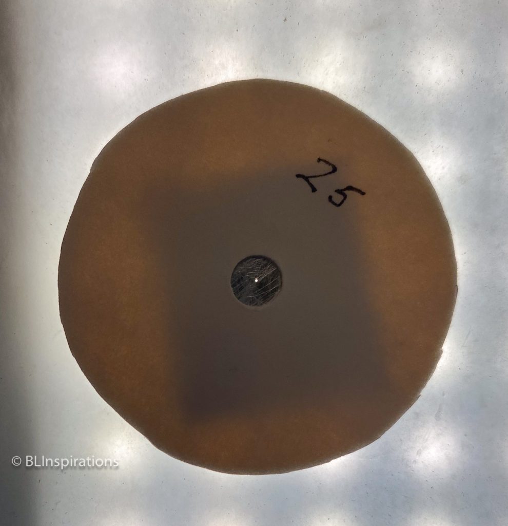
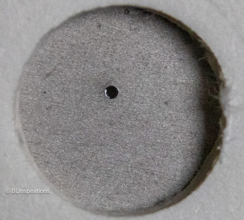
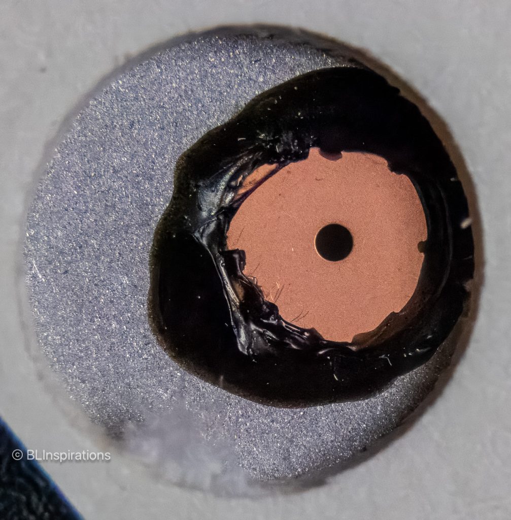
The 0.30 pinhole was chemically etched, broached, and deburred in a 0.003” (0.076 mm) thick stainless-steel disk about 7/8” diameter. Although thinner than the aluminum beverage can material, it was stiffer and easier to handle. The 0.50 mm pinhole was laser drilled in 0.002” (0.05 mm) thick copper which was then mounted on a 1½” diameter, 0.024” (0.6 mm) thick aluminum disk.
These images show the two commercial pinholes mounted on substrates.
Pinhole Images
44 mm focal length images
At different times during this project I mounted my camera on a tripod just outside our back door and took photos with both a lens and various pinholes. I also used the 3 pinholes in one foil substrate and a 1.62 mm pinhole made from an aluminum beverage can. For comparison with the outdoor images, I also took some photos of small objects arranged on a tabletop – these objects were 20” front-to-back and with the regular lens I focused on the objects at the back.


44 mm Focal Length Exposure Information
This exposure information is in the same sequence as the gallery above.
Regular lens
- Lens: 44 mm, f/8
- ISO: 200
- Shutter: 1/100
0.32 mm foil pinhole
- ISO: 3200
- Shutter: 1/5
0.30 mm etched pinhole
- ISO: 3200
- Shutter: 1/8
3 pinholes in foil
- ISO: 3200
- Shutter: 1/4
1.62 mm can pinhole
- ISO: 3200
- Shutter: 1/125
Regular lens
- Lens: 44 mm, f/16
- ISO: 200
- Shutter: 1/250
0.28 mm can pinhole
- ISO: 1600
- Shutter: 1/20
0.30 mm etched pinhole
- ISO: 1600
- Shutter: 1/20
3 pinholes in foil
- ISO: 3200
- Shutter: 1/50
1.62 mm can pinhole
- ISO: 3200
- Shutter: 1/1000
Regular lens
- Lens: 44 mm, f/22
- ISO: 100
- Shutter: 1/5
0.28 mm can pinhole
- ISO: 1600
- Shutter: 1/2
112 mm focal length images
I took these photos at the same time as I took the 44 mm focal length images above.


112 mm Focal Length Exposure Information
This exposure information is in the same sequence as the gallery above, remember that the effective pinhole aperture is higher with the longer focal length.
Regular lens
- Lens: 117 mm, f/8
- ISO: 200
- Shutter: 1/30
0.48 mm foil pinhole
- ISO: 6400
- Shutter: 2.0
0.49 mm can pinhole
- ISO: 6400
- Shutter: 1.3
0.50 mm laser pinhole
- ISO: 6400
- Shutter: 1.3
3 pinholes in foil
- ISO: 6400
- Shutter: 4.0
1.62 mm can pinhole
- ISO: 6400
- Shutter: 1/6
Regular lens
- Lens: 109 mm, f/16
- ISO: 200
- Shutter: 1/320
0.30 mm etched pinhole
- ISO: 3200
- Shutter: 1/15
0.50 mm laser pinhole
- ISO: 3200
- Shutter: 1/20
0.46 mm can pinhole
- ISO: 3200
- Shutter: 1/13
3 pinholes in foil
- ISO: 3200
- Shutter: 1/8
1.62 mm can pinhole
- ISO: 3200
- Shutter: 1/160
Final Thoughts and Suggestions
- Be careful of moisture, dust, and dirt – the sensor is exposed
- Forget the viewfinder and use live view
- Shoot for shapes and contours – not sharp edges
- Expect long exposure times, high ISO’s, and lots of noise – use a tripod
- Try multiple pinholes to get multiple exposures in a single image – experiment with different pinhole shapes such as square or star-shaped.
- Hand-held camera movement can yield interesting results
- Some images look better in black and white
- Learn by experience and experimentation – have fun!
References
- https://en.wikipedia.org/wiki/Pinhole_camera
- https://en.wikipedia.org/wiki/Camera_obscura
- https://digital-photography-school.com/how-to-turn-your-dslr-into-a-digital-pinhole-camera/
- https://www.bhphotovideo.com/explora/photography/tips-and-solutions/f256-tips-for-digital-pinhole-photographs
- Making, Measuring and Testing the “Optimal” Pinhole: Pinhole Adventures Part 3 – by Sroyon